by Arqai Ne’urin

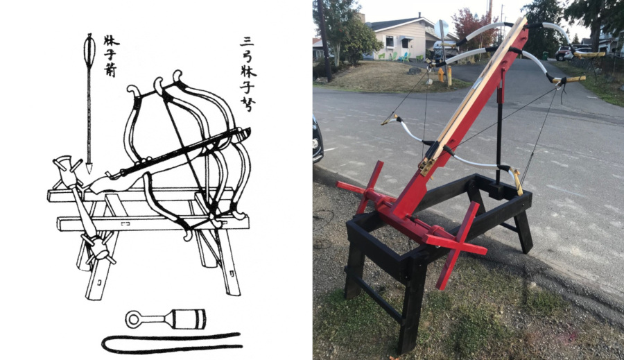
San Gong Chuangzi Nu from the
Wu Ching Tsung Yao, the Most Important Developments in the Military
a Song Dynasty document dated approximatley 1040 AD
Context
What is it?
- “Bow of the Ox” Kaman-i Gav, references in Juvaini History of the World Conqueror,translated by John Andrew Boyle, 1958 – mentions a powerful engine used by Hulegu to defeat the Assassins (1260 CE).
- Tabakat-i-Nasiri translated by Major H.G. Raverty – mentions an engine with three bows pulled by a single string, also used by Hulegu
- Wu Ching Tsung Yao (Collection of the most important Military Tactics), Song Dynasty (1040 AD) document – Has a lovely picture of “Sang Kung Nu”, three bow crossbow. This is my reference image for this project. (See cover image)
When is it?
- Wu Ching Tsung Yao – It was important enough to make it into this document in 1040 AD so it was likely around earlier
- Hulegu used something like it in the Battle of Ain Jalut (1260 CE) as documented by Juvaini and Raverty
Where is it?
- Wu Ching Tsung Yao puts it in Central China
- History of the World Conqueror puts it in the Middle East
How does it work?
- Lots of theories from all around the world, but I can’t find anyone who REALLY knows. Gonna have to build one to find out.
- Okay, that’s rather misleading. It was my intention from the very start to build one.
- Modern “recreations” have been more artistic and fanciful than scientific. Some of the recreators are very critical of the designs of others. There is no consensus. There is criticism of my engine as well. But I DO have an engine. And it works.
- I’ve only seen one other actual functional build, and I’m pretty sure they cheated. (We can discuss this if you like, but it really doesn’t have anything to do with my own efforts.)
Experimental Archaeology
While it would have been possible to use period materials and methods, that wasn’t the goal. The goal is to find out how it works and build a working model. Using modern methods produced a working model that is functionally identical to its period counterpart. It looks and functions in the same manner as the engine that inspired it. Also, the working model is suitable for use on the SCA battle field. As it is, using modern materials and methods took me five years to get a functional engine. I simply don’t have the time to invest using slower means.
By the time of the Song Dynasty (960 – 1270 CE), the Chinese government was at the head of the equivalent of our modern “Military/Industrial Complex”. Need to outfit five thousand new crossbowman conscripts? No problem. Everything is in inventory. The components of the trigger mechanisms are mass produced and entirely interchangeable from one to another. We know this from extant archaeological evidence.
An engineer could walk down to the armory and select the pieces he wanted to use and put them together in any way he wanted. Any parts that weren’t already in inventory he could have specially made by a skilled specialist craftsman. Our engineer could just keep trying new configurations until he found the one that worked best. I don’t have that luxury. I have to figure out what works best by trial and error. And I am my own manufactory.
The Bows
Attempt 1
The first set of bows was stacked bamboo. They looked a bit like a truck spring. This method was used in period for crossbows (ref. 3). I tried many configurations, with and without siyahs, with and without additional hardwood slats. I couldn’t make them work reliably. And they kept breaking when I was trying to get to legal SCA combat range. I was investing too much time trying to figure out how to make bamboo bows and wasn’t getting anywhere. Also, suitable bamboo for this sort of thing was getting harder to find and cost was becoming prohibitive. Time to move on.


Attempt 2
The next attempt at bows was layers of hardwood, backed with fiberglass. This was thought to be a reasonable approximation of a ‘wood/sinew/horn’ bow that would have been used in period. A few attempts showed that I didn’t know enough about working with the different types of fiberglass available, and also, the failures were getting expensive. There’s that steep learning curve again. I’m spending too much time climbing Mt. Stupid. Moving on again.

Attempt 3
The final set of bows that I made are the best bows I have the skills to make. They consist of two layers of hickory hardwood (incredibly tough) with an ash hardwood siyah. They are tapered and shaped to a ‘D’ cross section. And they worked. Until I broke them. During testing, I was trying to get to the minimum range for SCA siege combat of 40 yards. My best test shot went 38. I reconfigured the engine for a longer cast and as I was drawing it, the middle bow popped.

Even though they broke, that last set of bows was a success. I knew what draw weights I would need. The bows I made scaled to 30#, 30#, and 60# each, front to back. I now know the proportions I need and also know they need to be heavier.
Current Bows
It was decided to just purchase modern fiberglass bows in the weights that I needed. It’s what our period engineer would have done. Just go to the armory and get what you need. Besides, modern fiberglass bows by a reputable maker are a LOT safer than anything that I was able to come up with. This project does end up in SCA war scenarios, after all.

The bows installed in the engine today are AMO at 55#, 60#, and 110# respectively, front to back. They consistently throw an SCA siege legal munition to the required distance without failure.
Bows Summary
My research indicates that the math for the weight of the bows is simply 1, 1, 2, meaning the rear bow (reverse facing) needs to be equal to the weight of the other two (with some consideration for mechanical losses due to friction on the bowstring). The question arises as to why, then, use two bows in the front? Why not just use two bows of equal weight with one reversed. I believe this is due to the speed at which the bows release. The lighter weight bows release faster than the heavier reversed bow. This is critical to keeping the bow string taught. If the reversed bow releases faster, then the bow string could go slack during release and this could result in catastrophic bow or string failure when the slower bow finally catches up.
Important Update: It was noted that when winching the bowstring back, the front bows draw as expected, but the rear bow actually relaxes slightly. Once the front bows reach a certain draw, they stop moving and the rear bow begins to draw. This shows that the smaller bows do indeed draw first. It doesn’t prove my theory that they move faster, but it does show that I’m barking up the right tree. I’ve since taken some slow motion video that confirms this hypothesis. Drawing or releasing, the front bows move first. When they’re done, the big back bow takes over. To examine this further, more testing is warranted. I’m looking into getting heavier bows for the front to balance things out a bit more.
The Tiller
It’s a stick. With holes in it. How hard can that be? Plenty as it turns out.
Turns out the location of the holes, where you mount the bows and trigger, is pretty critical.
Attempt 1
As such, the first “tiller” was a simple 2 x 4 with notches cut for the bows. These would have been the bamboo “truck spring” style. I had no idea how far those bows would flex, so I started with just one notch for one bow. I strung the bow and pulled it back and marked the spot on the tiller. I then measured the distance from the belly of the bow slot to the mark, doubled that distance and cut the notch for the reversed bow at that point. I assumed that both bows would have to flex the same amount. I put two bows of equal draw weight into the slots and strung them with a single string. I pulled that string back, drawing both bows. As such, the string travels twice as far as a normal bow string. I marked the point on the tiller where the bow string landed. That’s where my trigger needs to be. And the slot for the third bow? It’s not so critical. It can be at any convenient distance forward of the middle bow. I didn’t know this at the time, but it works out that way.

Tiller mock up, to determine spacing of the bows
Note, these were the first bows, simple stacks of bamboo, bound with jute cordage.
That’s the basis for where the bows and trigger get mounted. I used that same idea and method for all subsequent tillers.
Attempt 2
The second tiller was the first actually made to be used. It consisted of a 2 x 6 with the notches placed as above. I didn’t have a real trigger yet, but had an improvised one located as above. Each bow was tied in to the tiller with jute cordage around a peg that extended from the bottom of the tiller. A rail to guide the projectile was attached to the top of the tiller. This first engine wasn’t pretty, but it worked. Sort of. I didn’t get any where near legal minimum range. I ended up reworking the tiller a few times to suit stronger and thicker stacks of bamboo. This tiller was retired the at the same time as the idea of bamboo bows. It had been modified so many times it was no longer practical to continue.

This is the second tiller built and the first intended to be used.
Note: Nothing you see on this engine is on the final version.
It’s all been replaced with something better.
Except the experience. I used a lot of that.
Attempt 3
What you see on the the engine today is the third tiller (any of the images in this article where the tiller is painted red). It is the culmination of all that was learned in the previous processes. One of the big issues I had with tiller #2 was that it kept wanting to warp or crack along the wood grains. For this reason, tiller #3 is built up from three layers of plywood. It is dimensionally stable, stronger, and superior to the 2 x 6 version, even though the dimensions are approximately the same. The notches for the bows and the cut-out for the trigger are based on the same calculations as the original prototype tiller.
You may notice that the cut outs for the bows are a bit odd. That is because there were at least two other versions of bows that were fitted in this tiller before the decision to go with professionally built bows was made. But the math stays the same. Those smaller notches were to suit bows that I had made (and subsequently broke).

The top rail for tiller #3 is made of hardwood (maple). Previous versions were pine and showed signs of wear and friction from the bow string. This one is well oiled and smooth. It is detachable, though I doubt I will ever need to replace it. This method also helps to secure the bows into their slots.
The Trigger

Chinese crossbow triggers are pretty well documented. You can find extant examples in museums and books readily. The way you hear it, it seems you can’t plow a field in China without digging one up. The design was VERY successful, and as with any successful technology, it got used a LOT. Triggers of this design are found as early as Qin (the terracotta army used them) and as late as Ming (even though crossbows were being replaced by gunpowder weapons), and even today. Modern replica crossbows often will use a design similar to this.
But all I had were pictures, and those usually were of a single view, presented from the side. There was one three dimensional view in Chinese Archery, by Stephen Selby (ref. 3) that sort of showed how the pieces worked. I was resolved to having to figure out the actual mechanism on my own.
Rushed temporary trigger
The first trigger was a simple pin and lever design. Period, but never intended for the long term. I mention it here only grudgingly because it was part of the process and shows up in some of my pictures. It was ugly, barely functional and soon discarded. I found the lever amongst the junk in my shop.

Ugh. Just looking at this now is painful.
Photo Credit: Theodoric the Scholar (Derek Lyons) used with permission
Prototyping the trigger
I built two prototypes out of wood. The first was just to prove that I understood the mechanism. The second proved that the ideas worked when scaled to approximate dimensions. So I started cutting steel to make one of my own.


dimensions and does it still work? Yes.
Trigger build progression
I had the trigger lever cut out of steel when Magister Arion the Wanderer put one of these triggers in my hand and said, “Why don’t you use this?” It was rough castings (still had mold flashings on the pieces, etc.) by a modern bronze artist who had based his work off of an existing trigger mechanism. Magister Arion tasked me with cleaning up and fitting the rough castings into a functional trigger. I did so, but it soon became apparent that I would have to make some rather dramatic changes to this trigger to better suit a siege engine. I was loth to do so, so I ended up making one of my own.

The first issue with Arion’s trigger was that it released far too easily. The seer and the trigger lever engagement would best be described as a “hair trigger”. So I made a new trigger lever and seer out of brass (see a photo of these pieces in the trigger appendix). That worked pretty good, but now they don’t fit into the box housing and mounting the bronze box housing in the tiller was awkward. As such, I made side plates out of steel to house the parts. But then I realized I had to make changes to the trigger nut. As this was part of a functional trigger already, I chose to make one of my own. The originals were cast as a single object out of bronze. I don’t have the skills or facilities to cast bronze. But I can cut brass. So my trigger is machined and assembled from brass bar stock. Once I had the brass nut the way I wanted it, the first seer and trigger lever I had made were too loose, so I made new ones of those as well. With all the working parts now being of my own manufacture, it only made sense to make the box frame and the pins as well. I’ve documented the trigger manufacture in an appendix.

Note: the top rail for the projectiles is not yet installed in this picture.
The timing of the trigger manufacturing was about the same time as when the decision was made to stop using bamboo bows. Also about the same time as the need for a new tiller.
The Base and Windlass
Cue the maniacal screaming.
The first base I made was full of mistakes. First, I tried too hard to make it look the the drawings in Wu Ching Tsung Yao. Not only did it end up NOT looking much like the original drawings, it was wobbly, unstable, poorly designed, and of inadequate materials. The base was primarily made from salvaged 2 x 6 lumber. I tried using joinery that I am not familiar with and it showed. I ended up stabilizing it with rope cross-ties just to make it functional. It also had the windlass mounted through the side rails. This is NOT true of my reference drawing, but was based on some one else’s idea of a “better way”. Not.
Speaking of the windlass, it worked. Mostly. The handles collided with the extensions of the base frame cross-pieces and they had to be modified.

That’s the original winch axle in the foreground end.
I’m so glad this part of my life is over.
So, when everything else was being reworked, it was obvious that the base needed to be replaced as well.
The old base had a lot of problems with splitting along the wood grain. That was eliminated in the new base by the decision to go with stacked layers of plywood.
The new base was originally built about ten inches longer than what you see today. I wasn’t entirely sure where and how I was going to mount the windlass. Turns out the extra length wasn’t needed.
In my reference image, the windlass looks like it’s just sitting on top of the frame rails (see cover image). Obviously, that wouldn’t work, so I experimented with a few ideas and settled on what you see today (see any of the pictures in this article where the engine is painted). It works well and looks sufficiently like the reference drawing to suit my tastes.
Latest Iteration
So that’s what got me here.

- The base frame and tiller are three layers of half inch marine grade plywood. The base is made to fold flat for easier storage and transport.
- The top guide rail of the tiller is hard maple, oiled and polished.
- The winch is a one inch steel pipe, threaded on the ends to accept flanges that support the winch handles. There are steel pins mounted to engage the winching lines. There are decorative bolsters to make the winch look more like the period reference drawing and to space out the winching handles.
- The trigger is machined from half inch brass bar stock in a housing machined from quarter inch brass bar stock. The pins are half inch brass round bar with half inch brass bar heads. All stress points on the trigger and housing are pinned for strength.
- The bows are fiberglass recreations of an Asian style bow from the period. They were purchased from a Chinese manufacturer.
- All cordage is para-cord for durability and strength, including the main bow string. The main bow string is a heavier rated para-cord, better suited to this purpose.
On The Field
Operation in SCA war scenarios requires two crew members, as this is classified as a “Class B” engine. In a practical sense, one crewman will operate on each side of the engine. The windlass has handles on each side (as does the engine in the reference drawing) to make this quick. This crew arrangement also works well for hooking the winching lines to the bow string. Commands should be given audibly by the crew leader. Once the engine is charged, one crew member loads the munition and the other prepares to fire. The first video linked below shows some of this operation, though not in actual SCA combat.
Release is smooth and quiet. In the din of battle, targets don’t realize a shot has been fired until they are very dead. The engine has an effective range from 30 feet (minimum legal shot distance for this type engine) out to about 25 yards. While the engine is capable of firing as far as 65 to 70 yards, targeting at those ranges is difficult, especially with the prescribed SCA legal munitions. At those longer ranges, the tactic is to shoot into a crowd and hope. That usually is sufficient for a kill.
This engine is also very well suited to be operated by a single crewman for target activity. Different munitions, wood shafted with a steel tip, suited for target use are more precise and fly further with more stability.

They fly much better than combat munitions and have proven to be deadly accurate.
What’s Next?
- Get some heavier draw bows on the front. I hope that will get more draw from the big bow in the back to balance things out more.
- Data collection by instrumentation. I want to actually scale the draw weight of the bows. Additionally, I’d like to get a chronograph to shoot through to get projectile velocity.
- There are other ways to configure the bow string. I may play around with some of them. In trials, I couldn’t make them work well, so I went with the current method. But I know more now and would like to try again.
- Reconfiguring the bow string is likely to require me to make more bows. So here I go again, climbing Mount Stupid.
- Target Siege in the SCA is now a thing. The Society Earl Marshal approved my request early in 2020 and authorized Target Siege as an official “Experimental Program”. An Tir is “ground zero” for this program and the Barony of Dragon’s Laire is taking it very seriously. Specialized steel tipped munitions and a full set of rules have been developed. Once the world opens up again, look for Target Siege at an event near you.
Appendix — Trigger Development
You’ve already seen a picture of the ugly, rushed prototype trigger. Please don’t ask me to show it again.


The bow string didn’t engage or release as smoothly as I would like using the cast bronze nut. Since it was already part of a working trigger, I didn’t want to change it, so I had to make one of my own. I don’t know how or have the equipment to cast bronze, so I had to make other plans.


After that, it’s just file and sand to shape to clean everything up. I’ve made a few modifications to the nut since this photo in order to improve how it works, but this outlines the most difficult parts.
I don’t have photos of how I made the box frame for the trigger, but it utilized a lot of the same processes. Cut the pieces, drill them, pin them, and solder it all when you’re done.

Links to Videos
You can’t tell in the video, but I really did hit the target. 🙂
Bibliography
- 1. Chinese Siege Warfare: Mechanical Artillery & Siege Weapons of Antiquity, An Illustrated History – Liang Jieming – Copyright 2006, Leong Kit Meng ISBN 981-05-5380-3 (I am now “Facebook Friends” with the author. Cool guy. He’s asking me lots of good questions.)
- 2. “The Bow of the Ox”, by Edward McEwen in the Journal of the Society of Archer-Antiquaries, vol. 28, 1985.Mr. McEwen makes further references to scholarly works based on period information. I am including them here, but I don’t have ready access to the original references, only Mr. McEwen’s excellent article.
2A. ‘Ata-Malik Juvaini, The History of the World Conqueror, translated by John Andrew Boyle, 1958, Vol. II, pages 630-631
2B. Maulana, Minhaj-ud-Din, Abu-Umar-i-Usman, Tabakat-i-Masiri, translated from the Persian by Major H.G. Raverty, Vol. II page 1191
2C. Tseng Kung-Liang, Wu Ching Tsung Yao (Collection of the most important Military Techniques) originally written in 1040 AD - 3. Chinese Archery, by Stephen Selby, Copyright Hong Kong University Press, 2000, ISBN 962 209 501 1
- 4. “Chinese Crossbow Locks” by Edward McEwen in the “Journal of the Society of Archer-Antiquaries”, 2012
- 5. Chinese Crossbow Lock” by Lt.-Cdr. W.F. Paterson “Journal of the Society of Archer Antiquaries”, Vol. 11, 1968

Very interesting. I’ve wondered about the functionality of the triple crossbow since first hearing of it. I notice that when the engine is in the “ready to fire” position (as in https://athenaeum.baronyofmadrone.net/wp-content/uploads/2020/07/Painted-and-drawn_01-768×1024.jpg) the bows don’t appear to be flexed as much as they would be when held at full draw by a human archer, so I wonder what the engine’s draw poundage is, both when strung and ready to fire. Presumably it’s well short of #60 plus #30 plus #30 you’d get from adding the individual bows’ max draws together.
Could you provide some dimensions for the engine? Especially the drawlength, which looks impressively long for a crossbow (presumably due to the pulley effect doubling the distance).
Looking forward to the results of you experimentation with other bow strengths & string arrangements plus the instrumentation date. Keep up the good work!
To ensure that your string setup is correct, you need to measure the poundage on that string. From my own understanding and experience in geometry of bows, your current setup will essentially half the total poundage of the forward 2 bows. The rear bow is also setup to further reduce the effectiveness of the bow. You can see it if you visualize it from a pulley system view. The original drawing clearly does not show any use of pulley. The string attachment has to be exactly as the original drawing, but must make the rear bow larger, thus engulfing the forward bow. When the string is drawn, the rear bow will be pulled inward.
Regarding string set up. I noted in my text that there are other ways of arranging the string. The method I used is just one plausible configuration. Now that I have a working engine, I plan to look into other methods. I’ve not actually scaled the overall engine nor any of the individual bows as installed, but that is also on the agenda. Keep in mind that the bows in this engine don’t work in a conventional manner, meaning the string pulls more perpendicular to the bow than parallel to it. I am also planning on using a chronograph to clock the velocity of the projectile as it leaves the engine. All this is “future work”.
Regarding pulleys. It is important to remember that the artist that produced the original drawing may or may not have fully understood what he was looking at. The fact that there are no pulleys shown does not over-ride the fact that the engine cannot work without them. The original drawing suggests that the string is simply looped over the middle bow. This would introduce a huge amount of friction into the process and make the mechanics unpredictable at best, or catastrophic at worst. That said, I didn’t use pulleys. I used welded “D” rings mounted on cordage to allow the angle to self-adjust as the bows are drawn.
In the end, I have a working engine, based solely on a single historical drawing. Do I have it absolutely perfect? Absolutely not! But it does work.
Thank you for your interest in my work. If you have other period sources that would enhance this project, I’d dearly love to see them!
Very interesting and I would like to try my hand perhaps at something like this but I have become intrigued by the circadia or two bed engine. Any thoughts on that?
Your engineering chops certainly show in your decisions and work. It is amazing to see how many different mechanisms have to work, all in concert, for this to function. Thanks very much for an engaging write up and for sharing the reasoning behind making changes to your decisions. I love experimental archaeology!
Merci, monsieur.
Madame Jaqueline
Great read and a significant accomplishment! I very strongly recommend you look into sourcing mulberry wood. One of the great tragedies of SCA recreation is the prevalence of plywood – it’s perfectly period for Roman and some Celtic shields, but not for very much else. Indian or Chinese mulberry is the traditional wood for field hockey sticks and it is CRAZY strong and resilient, I believe only American hickory is tougher.
The scope of this project was to find out how the engine works and to make a working model suitable for SCA combat scenarios. Period materials and methods were not considered. However, I am considering making changes to this engine with more period materials in mind. As to bows, the last set of bows I made was made of hickory. I broke them. Well, one of them. I AM considering trying again. Playing with alternative string arrangements will likely require some more custom bows. I’ll look into mulberry, but I really liked working with the hickory.
I seem to remember seeing this somewhere … great work on a long term project … well written … well done indeed!
While this project may have been possible without your input and support, you certainly expedited it a great bit and made it a LOT more fun. Thank you for being a part of this crazy idea of an experiment.
Really interesting work! I didn’t even know something like this existed. Well done!
In certain circles in Chinese Archery forums etc., it’s fairly well known. Lots of “experts” will happily tell you all about it. Then I post pictures and video of my engine and it’s like, “Holy CRAP! Some one built one and it WORKS!” Now they’re all asking ME questions. 🙂
This is still amazing and following the progression of the attempts is great for people interested in experimental archaeology. It won’t always work the first time and having that expectation and studying the results for future improvements is a must!
Looking forward to a return to activities that will allow at least practice use
Yeah, it’s been a process, that’s for certain. The number of failed bows alone speaks to that. But there was always that part of me that said, “It _should_ work! What are you doing wrong?” And I’d get back into it again. Even now, when I have a working engine, there’s more I want to do.
This exhibit was an amazing read and I would love to see it in action (from the sidelines not in front of it)!
“Climbing Mount Stupid” is a great phrase and I have to agree that going and grabbing what you need from someone who knows how to make that part was likely the period appropriate method to take.
I am certain this is not your only amazing creation as it would be an amazingly hard place to start. What are some of your other siege engine creations, and what is next on your horizon?
Actually, this IS the first full scale engine I’ve built. I’ve built quite a few models to illustrate their function. I’ve also been involved in the build and maintenance of the Dragon’s Laire Baronial ballistae. And I’m an engineer by trade and a “manufacturing hobbyist”. So it wasn’t TOO much of a stretch for me to take this on. But I really couldn’t see building this to a smaller scale. My experience with models indicates that the math doesn’t always scale up proportionally to a full sized engine.
As to what’s next:
I’m helping Magister Arion build a “stone thrower” ballista.
I’m working with Milo of House Awry consulting on his in-swinger ballista.
The ever ongoing process of trying new things with this engine, including:
Better efficiency and power (meaning, trying new bows)
A different string arrangement is possible, but I couldn’t make it work in my early efforts. But I’ve learned a lot since then.
A simpler method of mounting the bows that doesn’t involve tying them in. They’ll be clamped in place securely by the top rail.
A means of locking the legs in place.
Detachable wheels for the front legs to make it easier to move on the target range.
I find that surprising that this is your first full scale but now I am definitely looking forward to seeing more of your work on the field (hopefully on the sidlines on on my side). Please keep up the work and research.
Fascinating. Why does the back bow, closest to user, work more effectively at imparting its energy in that configuration as opposed to facing the same direction as the other two? Thanks for showcasing all this work!
Good question. By having that bow reversed, the bows pull towards each other. This makes a pulley arrangement, rather like a block-and-tackle. This gives a mechanical advantage as the string travels twice as far as it would if all the bows faced the same way. Twice the acceleration equals twice the force applied to the projectile.
Thanks for asking!
This is amazing!
Thank you! Mechanized violence is my geek!
Extremely well thought out presentation. It has been a intriguing and inspiring to watch the development process through the years. You have achieved an amazing level of practical, hands on knowledge through a great deal of hard work. As I said, inspirational.
It’s been a road, right? Thanks for your support all along the journey!
That is a REALLY cool project! I’m blown away by the amount of work that you’ve done. 🙂
YIS,
Brehon
Thank you for your interest. This is the kind of “hard work” that I really enjoy. 🙂